
1973–1987 GM Squarebody Factory Suspension Specifications
Archival chassis and suspension engineering tolerances for 1973–1987 Chevrolet C10/C20 and GMC K10/K20 trucks. Inspect factory coil spring load rates, multi-leaf spring dimensions, shock stroke lengths, and upper control arm alignment shims.
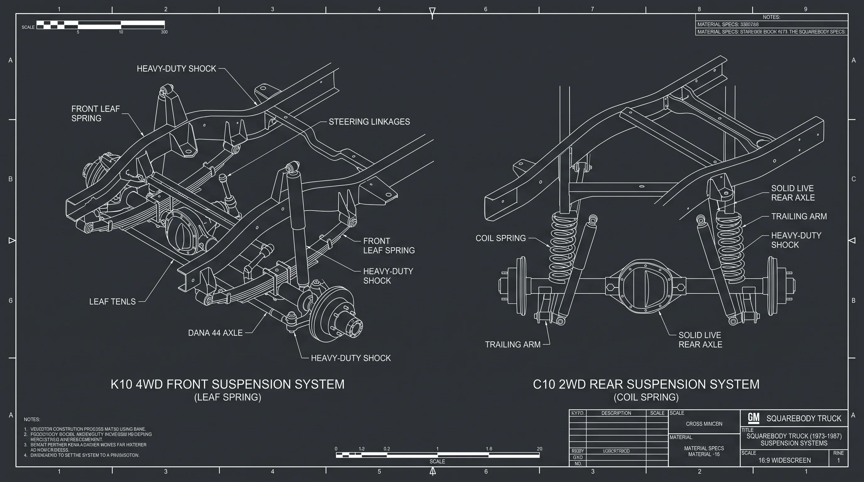
OEM Factory Suspension Specs & Alignment Comparator
Select any factory 1973–1987 GM Squarebody chassis model to inspect original coil spring rates, leaf spring arch dimensions, sway bar options, and alignment shim calculations.
Cross-Shaft Alignment Shim Quick Estimator
GM ST-330 ProcedureCalculate required cross-shaft shim pack changes to dial in caster and camber without trial-and-error:
Factory Suspension Architecture: 2WD Independent vs 4WD Solid Axle
The 2WD C10 utilizes stamped upper and lower control arms pivoting on pressed rubber bushings bolted to the heavy front crossmember. Steering knuckle ball joints feature a press-fit lower joint and a bolt-in/riveted upper joint. In contrast, 4WD K10/K20 models mount semi-elliptical multi-leaf spring packs directly beneath the front frame rails, supporting either a Dana 44 (1973–1979) or GM 10-bolt (1980–1987) front drive axle with open kingpin or ball-joint knuckles.
For lowering spindle geometry or 4WD leaf lift kits, see our comprehensive Suspension Lift & Drop Geometry Guide.
Factory Wheel Alignment & Control Arm Shimming Procedures
When aligning a C10 after replacing suspension bushings or ball joints:
- Camber Adjustment: Adding shims of equal thickness to both front and rear cross-shaft bolts pushes the upper arm outward, producing positive camber. Removing shims produces negative camber. Ideal street setting is +0.25° to +0.50°.
- Caster Adjustment: Caster is adjusted by changing the thickness difference between the front and rear shim stacks. Adding shims to the rear bolt (or removing shims from the front bolt) tilts the upper ball joint rearward, adding positive caster. Squarebodies benefit greatly from +2.5° to +3.5° of positive caster for stable interstate cruising.
- Toe-In Adjustment: Toe is set last by loosening the left and right tie rod adjusting sleeve clamps and rotating the sleeves until total toe measures 1/16" to 1/8" toe-in. Torque adjusting sleeve clamp bolts to 15 lb-ft with bolt openings pointing downward. Verify steering gearbox integrity with our Buyer's Frame Inspection Guide.
01 What are the factory wheel alignment specs for a 1973–1987 Chevy C10?
Factory GM ST-330 alignment specifications for a 2WD C10 pickup are: Caster: +2.0° to +3.0° (positive caster improves high-speed straight-line tracking); Camber: +0.25° to +0.50° (near zero to slight positive); Toe-in: 1/16" to 1/8" (total toe-in). Adjustments are made via shims placed between the upper control arm cross-shaft and the frame mounts.
02 What are the dimensions of Squarebody truck rear leaf springs?
Factory 1973–1987 GM Squarebody 1/2-ton pickups were equipped with either 52-inch or 56-inch rear leaf springs, both measuring 2.50 inches in width. The standard C10 shortbed utilized 52-inch springs (eye-to-eye along the arch), while longbed C10/K10 and 3/4-ton trucks typically featured 56-inch springs for a smoother unladen ride and higher payload capacity.
03 What front sway bar sizes came factory on Squarebody trucks?
Factory front anti-sway bars on 1973–1987 GM trucks came in 1.00-inch (standard light-duty C10), 1.0625-inch (1-1/16" intermediate F44 heavy-duty suspension), and 1.250-inch (1-1/4" heavy-duty C20/C30 and Big Block models) solid heat-treated spring steel diameters.
04 How do you tell the difference between 52" and 56" rear leaf springs?
Measure along the bottom arch of the main leaf from center of front eye bolt to center of rear eye bolt. In addition, on 52-inch springs, the center centering pin is centered (26" / 26"). On 56-inch springs, the centering pin is offset (26" front / 30" rear). Reversing 56-inch springs changes the rear axle position by 4 inches.

Dave Miller, ASE Master Automobile Technician
Lead Technical Reviewer & Restoration Specialist • ASE Cert #A1-884210 • 26+ Years GM C/K ExperienceDave Miller is an ASE Master Certified Automobile Technician (#A1-884210, A1–A8 plus L1 Advanced Engine Performance) with 26 years specializing in third-generation General Motors C/K classic truck restorations, drivetrain ratio calculations, and chassis wiring diagnostics. Operating from his independent classic GM restoration workshop in Ohio, Dave maintains an active archival library of physical 1973–1987 GM Factory Service Manuals (ST-330, X-7832). Every torque specification, mathematical gear ratio calculation, and bulkhead pinout on SquarebodyTech is personally reviewed and verified against original GM engineering standards.
Squarebody Engineering Architecture & Technical Pipeline
Complete subsystem hierarchy modeling powertrain, drivetrain ratios, factory electrical, and Phase 2 sister tools.
Powertrain & Small/Big Block Engine Specs
CID, horsepower, compression ratios, firing order, and valvetrain tolerances for 250, 305, 350, 400, and 454.
Automatic & Manual Transmission Ratios
TH350, TH400, 700R4, and SM465 continuous highway RPM, gear ratio, and rolling tire diameter solver.
Universal 13/17-Digit VIN & SPID RPO Decoder
ISO 3779 dual-format decoder for model year, assembly plant, GVWR series, and factory options.
Factory Electrical & Bulkhead Wiring Pinouts
1973-1987 firewall bulkhead connector pinouts, GM color standards, wire gauges, and ignition circuits.