
Squarebody Electrical Diagrams, Color Codes & Circuit Pinouts
Access authentic factory General Motors schematics for third-generation C/K-series trucks. Master firewall bulkhead pinouts, switched ignition feeds, charging harnesses, and lighting circuits with zero guesswork.
Firewall Bulkhead & Electrical Pinout Explorer
Inspect factory GM wiring color codes, circuit pathways, fuse ratings, and common failure points across ignition, starting, and lighting harnesses.
12V Constant Battery Power
Direct unswitched battery feed from the starter solenoid lug through two 16-gauge fusible links into the cab bulkhead.
12V Switched Ignition (Run & Start)
Hot in both RUN and START switch positions. Directly supplies primary 12V excitation power to the HEI distributor coil cap.
Starter Solenoid Engagement Circuit
Carries high-current solenoid trigger pulse when key is held in START. Common failure point is mechanical misalignment in column switch.
Accessory Power Circuit
Hot in RUN and ACCESSORY positions, dead during cranking (START) to reserve full battery amperage for starter motor draw.
Tail & Parking Lamp Circuit
Runs through firewall bulkhead to rear chassis harness along driver side frame rail to tail light junction.
Fuel Level Sender Circuit
Operates on standard GM 0–90 Ohm resistance sweep (0 Ohms = Empty, 45 Ohms = 1/2 Tank, 90 Ohms = Full). A disconnected ground registers as past Full.
Brake Stop Lamp & Hazard Circuit
Constant 12V battery power feeds brake pedal switch via orange wire; depressing brake outputs 12V via white wire into steering column turn signal switch.
How is the 1973-1987 GM Truck Electrical System Color-Coded?
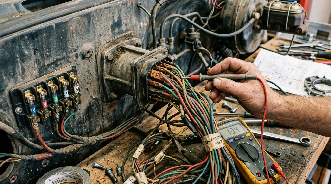
Factory 1973–1987 GM Squarebody electrical systems utilize a central firewall bulkhead connector dividing engine bay circuits from the interior cab harness. Standard GM color-coding routes 12V constant battery power via red 10 AWG leads, switched ignition via pink leads, starter solenoid engagement via purple leads to terminal S, and ignition coil power via pink wires (or resistance wire on pre-1975 points distributors).
Across C/K platforms (master GM truck guide), the 10 AWG red battery trunk connects the starter to the bulkhead, protected by molded 14 or 16 AWG fusible links against dead shorts.
Core Electrical Subsystem Vector Schematics
Select a core GM Squarebody electrical circuit to inspect component pinouts, factory wire color standards, and operational flow.
Ignition Switch, Starter Circuit & HEI Distributor Wiring
The steering-column-mounted Ignition Switch supplies 12V down a 12 AWG purple wire to terminal 'S' on the starter solenoid during cranking. Delco HEI distributor conversions require an un-ballasted 12.0V switched feed in CRANK and RUN. Discard the pre-1975 1.8-ohm resistance wire and run a 12 AWG pink lead from the fuse block IGN terminal. Observe clockwise Firing Order: 1-8-4-3-6-5-7-2.
Interactive Electrical & No-Crank Diagnostic Selector
3-step branching logic to isolate starter solenoid voltage, parasitic battery leaks, neutral safety switches, and wiper pulse boards.
Dual Fuel Tank Switching Valve Wiring & Fuel Gauge Circuit
Auxiliary fuel tanks (RPO NL2) feature 3-port (1973–1980) or 6-port Pollak valves (1981–1987) on the frame rail. The dash switch reverses polarity to toggle supply, return, and the 0–90Ω sender signal (tan/white lead). Frame rails also house neutral safety switches for TH350, TH400, 700R4, and SM465 via our transmission electrical specs.
Dual Fuel Tank Selector Valve & Solenoid Troubleshooter
Isolate 3-port solenoid (1973–1980) vs 6-port motorized Pollak valve (1981–1987) routing, dash switch polarity, and fuel gauge jumping.
Factory Instrument Gauge Resistance Specifications (Ohmic Calibration)
Factory 1973–1987 GM Squarebody instrument clusters utilize electromagnetic air-core gauges calibrated to precise resistance ranges. Testing sending units with a digital multimeter (DMM) against ground confirms whether erratic needle readings originate from sender failure, missing engine ground straps, or cluster printed circuit trace oxidation.
| Instrument Gauge | Zero / Empty | Mid-Scale | Full / Max | Sensor Wire Color | Common Diagnostic Fault |
|---|---|---|---|---|---|
| Fuel Level Gauge Sec 8C | 0 Ω (Empty) | 45 Ω (1/2 Tank) | 90 Ω (Full Tank) | Tan / White (18 AWG) | Needle past 3 o'clock indicates broken ground strap. |
| Coolant Temp Gauge Sec 8C | 350 Ω (100°F) | 150 Ω (180°F) | 65 Ω (220°F Hot) | Dark Green (18 AWG) | Teflon tape on threads insulates sender body. |
| Oil Pressure Gauge Sec 8C | 0 Ω (0 PSI) | 30 Ω (30 PSI) | 60 Ω (60 PSI) | Dark Blue (18 AWG) | Shorting blue wire to ground drives needle to 0 PSI. |
| Battery Voltmeter Sec 8C | 10.0V (Discharge) | 12.6V (Resting) | 14.2V (Alternator) | Pink (IGN Switched) | Needle below 12V while running indicates failed diode. |
Battery Relocation Cable Gauge & Maximum Allowable Voltage Drop
Relocating the battery to the rear truck bed or passenger frame rail requires properly sizing conductor cables to prevent hot starter cranking failure. Starter solenoids draw between 180A and 250A during initial engine roll-over. To keep total cranking circuit voltage drop below the SAE J541 standard of 0.50V across an 18-foot run, utilize 1/0 AWG or 2/0 AWG pure copper fine-strand welding cable with a dedicated ground return strap directly to the engine block.
Frequently Asked Questions About Squarebody Electrical Problems
01 Why does my fuel gauge read past full on a GM Squarebody?
A fuel gauge pegged past full indicates an open circuit (infinite resistance) between the tank sending unit and gauge cluster. GM fuel senders operate on a 0-90 ohm standard (0 ohms = Empty, 90 ohms = Full). Common causes include a broken pink/tan wire along the frame rail, a disconnected ground wire at the frame crossmember, or an oxidized dash printed circuit board connector.
02 Can I power an HEI distributor with the original 1973–1974 points wire?
No. Pre-1975 points ignition systems used an intentional 1.8-ohm resistance wire to step down running voltage to 9–10V to prevent burning points. An HEI distributor requires a full 12.0+ volts during both cranking and running. Running HEI on resistance wire causes weak spark, high-RPM misfires, and hard hot-starts. Replace this circuit with a direct 12 AWG pink wire from the fuse panel IGN terminal.
03 What causes headlights to flicker or cut out entirely on Squarebody trucks?
Headlight cutout is triggered by the thermal internal circuit breaker inside the factory headlight switch. Halogen conversions pull higher current through aged factory 16 AWG wiring and corroded bulkhead pins, causing heat that trips the thermal breaker. Installing an external dual-relay harness draws high current directly from the battery/alternator post, relieving cab switch load.
04 How does the dual fuel tank solenoid valve switch on 1973–1987 trucks?
GM used two primary designs: a 3-port vacuum/solenoid valve (1973–1980) and a motorized 6-port Pollak-style valve (1981–1987). The dash switch directs 12V power to energize the solenoid or reverse polarity on the motorized valve to toggle supply and return lines while simultaneously toggling the 0–90 ohm fuel gauge sender lead between left and right tanks.
Squarebody Engineering Architecture & Technical Pipeline
Complete subsystem hierarchy modeling powertrain, drivetrain ratios, factory electrical, and Phase 2 sister tools.
GM Truck VIN & RPO Decoder
Dual-format decoder for model year, plant, and SPID RPO codes.
Transmission Specs & RPM Simulator
Highway RPM and gear ratio solver for TH350, TH400, 700R4, SM465.