
1973–1987 GM Squarebody Body Restoration & Sheet Metal Guide
Comprehensive sheet metal repair procedures, factory steel gauge specifications, yellow pine bed wood blueprints, and structural door hinge rebuilding for classic Chevrolet and GMC third-generation C/K trucks.
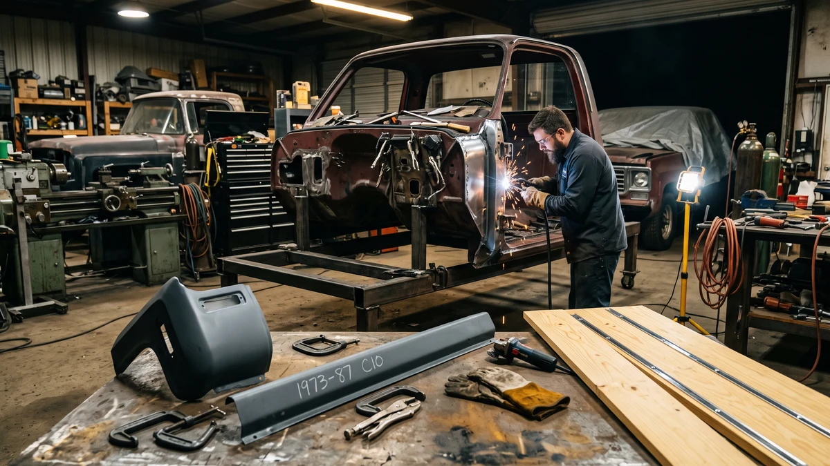
Where Do GM Squarebody Trucks Rust and Why Do Cab Corners Fail?
1973–1987 GM Squarebody trucks suffer from predictable localized corrosion in four primary zones: rear cab corners, inner/outer rocker panels, front floor footwells, and lower front fenders. Cab corner failure is caused by factory roof drip rail seam sealer drying and cracking over time, allowing rainwater to funnel down the internal B-pillar cavity into the enclosed lower cab pocket where road debris and lack of drainage create a perpetual wet compost trap.
Unlike modern vehicles engineered with two-sided galvanized coatings, third-generation C/K trucks (including the master Squarebody chassis line) relied on single-sided primer baths. Over decades, chassis vibration breaks down seam sealer between cab back and floor flange, allowing trapped moisture to perforate 18-gauge steel from the inside out.
Cab Corner Rust Remediation: Step-by-Step Welding Protocol
Proper cab corner replacement requires cutting out all pitted metal rather than simply welding a slip-on patch over active oxidation. Follow this factory-grade restoration procedure:
- Step 1: Clean & Strip Substrate: Strip paint 4" past rust margins using an 80-grit flap disc to expose factory spot welds.
- Step 2: Drill Spot Welds: Release cab corner from floor flange using a 5/16" Blair spot weld cutter without piercing inner backing sheet.
- Step 3: Scribe Cut Line: Overlay stamped 18-gauge replacement panel. Scribe 1/2" below intended seam; cut with reciprocating saw or 1/16" cutoff wheel.
- Step 4: Cavity Prep & Weld Primer: Clean internal pocket. Apply phosphoric acid rust converter followed by two coats of zinc weld-through primer.
- Step 5: Fitment & Clecos: Clamp replacement panel with Cleco fasteners maintaining a uniform 0.040" (1.0 mm) root gap.
- Step 6: Stitch-Tack Welding: MIG weld with 0.023" ER70S-6 wire and 75/25 Ar/CO2. Space tacks 2" apart, cooling with air to prevent oil-canning.
Cab Corner & Rocker Seam Exploded Vector Architecture
Inspect the 3-layer pinch weld flange sandwich, locate factory spot welds for drilling with a 5/16" Blair cutter, and trace water entrapment vectors inside the B-pillar cavity.
Inner & Outer Rocker Panel Replacement (Mandatory Structural Bracing)
Rocker panels form the longitudinal stiffness bridge connecting firewall cowl to cab wall. Cutting without structural cross-bracing causes cab sag and permanent door gap misalignment.
| Component | Steel Gauge | Structural Function | Attachment Spec |
|---|---|---|---|
| Outer Rocker Panel | 18-Gauge (0.0478" / 1.21 mm) | Exterior door sill & weatherstrip flange | Plug welds to top pinch; spot welds at floor |
| Inner Rocker Panel | 16-Gauge (0.0598" / 1.52 mm) | Longitudinal frame-to-cab beam stiffness | Rosette plug welds to cab floor step |
| Cab Floor Support | 16-Gauge (0.0598" / 1.52 mm) | Weight transfer to cab mount bushings | High-strength stitch welds to inner rocker web |
Mandatory Cab Bracing Protocol: Before cutting, tack-weld 1"x1" square tubing (0.083" wall) diagonally across open door frames from upper hinge pocket to lower striker pillar, with a horizontal spreader bar between B-pillars. Cross-reference our Squarebody wheelbase and chassis guide for frame alignment.
Factory Bed Wood Dimensional Blueprint: Yellow Pine & Skid Strip Specs
Factory 1973–1987 GM Fleetside and Stepside beds featured kiln-dried Southern Yellow Pine planks with precision-rabbeted edges interlocking with steel skid strips.
| Bed Type | Length | Planks | Board Widths | Strips | Rabbet Spec |
|---|---|---|---|---|---|
| Shortbed 6.5' (Fleetside) | 77-1/4" (1,962 mm) | 7 | Center: 7-1/4" • Inners: 7-1/4" • Outers: 5-1/4" | 8 | 1/2" wide x 5/32" deep |
| Longbed 8.0' (Fleetside) | 97-1/4" (2,470 mm) | 8 | Uniform 7-1/4" width across all positions | 9 | 1/2" wide x 5/32" deep |
| Stepside (6.5' Bed) | 77-1/4" (1,962 mm) | 8 | Center: 6-1/4" • Outers: 5-7/8" | 9 | 1/2" wide x 5/32" deep |
Finishing & Sealing: Sand through 180-grit, then seal all six sides (including end-grain) with boiled linseed oil/mineral spirits or marine spar varnish with UV inhibitors. Never assemble unsealed planks.
Saginaw Door Sag & Hinge Pin Rebuilding Protocol
Squarebody doors weigh over 65 lbs each. Sintered bronze bushings wear through after years of use, dropping the door at the striker.
- Pin & Bushing Specs: Hardened steel pins measure 0.342" (8.69 mm) OD with 0.415" OD flanged bronze bushings.
- Spring Removal: Always use a GM door spring compressor (KD 3392 or Lisle 44400) before driving out hinge pins.
- Hole Reaming: Drill elongated egged holes to 27/64" (0.421") and press in oversized bronze bushings with Loctite 680.
- Striker Alignment: Set door gaps to 3/16" uniform perimeter spacing and center striker cleanly inside rotary latch.
Cab Mount Bushing Replacement & Frame Alignment Specs
Worn cab mount bushings cause front sheet metal misalignment and hood-to-cowl rubbing:
- Position 1 (Radiator Core Support): 55 ft-lbs (75 N·m) with 1/2"-13 Grade 8 fasteners.
- Position 2 (Front Cab Floor): 50 ft-lbs (68 N·m) beneath footwells.
- Position 3 (Rear Cab Floor): 50 ft-lbs (68 N·m) at rear cab corners.
- Rubber vs Polyurethane: OEM rubber dampens vibration; high-durometer polyurethane (Energy Suspension #3.4116) maintains alignment under heavy torque.
Squarebody Restoration Budget & Parts Cost Estimator
Plan your 1973–1987 GM truck build costs with empirical parts pricing across five restoration disciplines. Toggle between Budget DIY, Street Performance, and Concourse OEM quality tiers with real-time financial tallies.
Loading restoration items...
Frequently Asked Questions: Squarebody Body Restoration
01 How do you keep the cab square when replacing rocker panels on a Squarebody?
Before cutting outer or inner rocker panels on a 1973–1987 GM Squarebody truck, you must install structural cross-bracing inside the cab. Weld 1-inch square steel tubing diagonally across each door opening (from the upper door hinge pocket to the lower striker pillar) and run a spreader bar between the left and right B-pillars. Keep the cab bolted to the frame on level jack stands to preserve door aperture geometry.
02 What gauge sheet metal did GM use on 1973–1987 Squarebody cabs?
General Motors built 1973–1987 C/K truck cabs with 18-gauge cold-rolled steel (0.0478 inch / 1.21 mm) for exterior outer skins including cab corners, door outer skins, and outer rockers. Inner structural channels, front floor hat supports, and inner rockers utilized heavier 16-gauge steel (0.0598 inch / 1.52 mm).
03 What are the exact factory dimensions for Squarebody shortbed wood planks?
Factory 1973–1987 GM shortbed wood floors require 7 kiln-dried Southern Yellow Pine planks cut to 77-1/4 inches long by 3/4 inch finished thickness. Each board features a 1/2-inch wide by 5/32-inch deep rabbeted rebate along both long edges to seat the 8 stainless steel skid strips.
04 How do you fix severe door sag on a Chevy Squarebody?
Door sag on Squarebody trucks is caused by wear in the factory sintered bronze hinge pin bushings. Rebuilding requires replacing the pins with 0.342-inch hardened steel pins and oversized bronze bushings (Dorman 38400 kit), compressing the heavy S-shaped detent spring with a specialized door spring tool (KD-3392), and re-aligning the striker latch on the B-pillar.

Dave Miller, ASE Master Automobile Technician
Lead Technical Reviewer & Restoration Specialist • ASE Cert #A1-884210 • 26+ Years GM C/K ExperienceDave Miller is an ASE Master Certified Automobile Technician (#A1-884210, A1–A8 plus L1 Advanced Engine Performance) with 26 years specializing in third-generation General Motors C/K classic truck restorations, drivetrain ratio calculations, and chassis wiring diagnostics. Operating from his independent classic GM restoration workshop in Ohio, Dave maintains an active archival library of physical 1973–1987 GM Factory Service Manuals (ST-330, X-7832). Every torque specification, mathematical gear ratio calculation, and bulkhead pinout on SquarebodyTech is personally reviewed and verified against original GM engineering standards.
Squarebody Engineering Architecture & Technical Pipeline
Complete subsystem hierarchy modeling powertrain, drivetrain ratios, factory electrical, and Phase 2 sister tools.
Powertrain & Small/Big Block Engine Specs
CID, horsepower, compression ratios, firing order, and valvetrain tolerances for 250, 305, 350, 400, and 454.
Automatic & Manual Transmission Ratios
TH350, TH400, 700R4, and SM465 continuous highway RPM, gear ratio, and rolling tire diameter solver.
Universal 13/17-Digit VIN & SPID RPO Decoder
ISO 3779 dual-format decoder for model year, assembly plant, GVWR series, and factory options.
Factory Electrical & Bulkhead Wiring Pinouts
1973-1987 firewall bulkhead connector pinouts, GM color standards, wire gauges, and ignition circuits.